USB flash drives are devices that are inserted and powered by USB ports. They store information and data that needs to be easily accessed. These devices are portable and convenient for people on the go. USB ports are a common necessity for students as well as business employees or personnel. In addition to convenience, they range in storage capacities from 1GB to 64 GB, so end users are able to store as much information as small computers.

USB Flash Drive and Card Reader
USB connects several devices to a host controller through a chain of hubs. In USB terminology, devices are referred to as functions, because each individual physical device may actually host several functions, such as a webcam with a built-in microphone. The hubs are special-purpose devices that are not officially considered functions. There always exists one hub known as the root hub, which is attached directly to the host controller.
These devices/functions (and hubs) have associated pipes (logical channels). The pipes are synonymous to byte streams such as in the pipelines of Unix. Pipes are connections from the host controller to a logical entity on the device named an endpoint. The term endpoint is also occasionally used to refer to the entire pipe.
These endpoints (and their respective pipes) are numbered 0-15 in each direction, so a device/function can have up to 32 active pipes, 16 into the host controller and 16 out of the controller.
Each endpoint can transfer data in one direction only, either into or out of the device/function, so each pipe is uni-directional. Endpoint 0 is however reserved for the bus management in both directions and thus takes up two of the 32 endpoints — all USB devices are required to implement endpoint 0, so there is always an inward and an outward pipe numbered 0 on any given device.
In these pipes, data is transferred in packets of varying length. Each pipe has a maximum packet length, typically 2n bytes, so a USB packet will often contain something on the order of 8, 16, 32, 64, 128, 256 up to 512 bytes.
The pipes are also divided into four different categories by way of their transfer type:
- control transfers - typically used for short, simple commands to the device, and a status response, used e.g. by the bus control pipe number 0
- isochronous transfers - at some guaranteed speed (often but not necessarily as fast as possible) but with possible data loss, e.g. realtime audio or video
- interrupt transfers - devices that need guaranteed quick responses (bounded latency), e.g. pointing devices and keyboards
- bulk transfers - large sporadic transfers using all remaining available bandwidth (but with no guarantees on throughput or latency), e.g. file transfers
When a device (function) or hub is attached to the host controller through any hub on the bus, it is given a unique 7 bit address on the bus by the host controller.
The host controller then polls the bus for traffic, usually in a round-robin fashion, so no device can transfer any data on the bus without explicit request from the host controller. Theinterrupt transfers on corresponding endpoints do not actually interrupt any traffic on the bus: they are just scheduled to be queried more often and in between any other large transfers, thus "interrupt traffic" on a USB bus is really only high-priority traffic.
To access an endpoint, a hierarchical configuration must be obtained. The device connected to the bus has one (and only one) device descriptor which in turn has one or moreconfiguration descriptors. These configurations often correspond to states, e.g. active vs. low power mode. Each configuration descriptor in turn has one or more interface descriptors, which describe certain aspects of the device, so that it may be used for different purposes: for example, a camera may have both audio and video interfaces. These interface descriptors in turn have one default interface setting and possibly more alternate interface settings which in turn have endpoint descriptors, as outlined above. An endpoint may however be reused among several interfaces and alternate interface settings.
Host controllers
The hardware that contains the host controller and the root hub has an interface geared toward the programmer which is called Host Controller Device (HCD) and is defined by the hardware implementer. In practice, these are hardware registers (ports) in the computer.
At version 1.0 and 1.1 there were two competing HCD implementations. Compaq's Open Host Controller Interface (OHCI) was adopted as the standard by the USB-IF. However, Intel subsequently created a specification they called the Universal Host Controller Interface (UHCI) and insisted other implementers pay to license and implement UHCI. VIA Technologies licensed the UHCI standard from Intel; all other chipset implementers use OHCI. The main difference between OHCI and UHCI is the fact that UHCI is more software-driven than OHCI is, making UHCI slightly more processor-intensive but cheaper to implement. The dueling implementations forced operating system vendors and hardware vendors to develop and test on both implementations which increased cost. During the design phase of USB 2.0 the USB-IF insisted on only one implementation. The USB 2.0 HCD implementation is called the Extended Host Controller Interface (EHCI). Only EHCI can support hi-speed transfers. Each EHCI controller contains four virtual HCD implementations to support Full Speed and Low Speed devices. The virtual HCD on Intel and VIA EHCI controllers are UHCI. All other vendors use virtual OHCI controllers.
Class Codes
The device descriptor of a USB device has a signature that tells what kind of device has been attached to the bus. This signature consists of class code, subclass code and protocol fields. Together, these identify what operating system driver should be used to communicate with the device. Additionally, each USB device interface descriptor contains the same signature fields. The interface signature allows multiple operating system drivers to simultaneously communicate with a single USB device (for example USB device with audio and video interfaces) and they also allow multiple instances of the same driver to communicate with separate interfaces of the same USB device (for example USB ethernet adapter with multiple ethernet ports)
Devices that attach to the bus can be full-custom devices requiring a full-custom device driver to be used, or may belong to a device class. These classes define an expected behavior in terms of device and interface descriptors so that the same device driver may be used for any device that claims to be a member of a certain class. An operating system is supposed to implement all device classes so as to provide generic drivers for any USB device.
Device class codes are decided upon by the Device Working Group of the USB Implementers Forum. If the class applies to the entire device, the class code is assigned to thebDeviceClass field of the device descriptor, and if it is to be set for a single interface on a device, it is assigned to the bInterfaceClass field of the interface descriptor. It is also possible that multiple interfaces of the device are grouped by using an Interface Association Descriptor, in which case the class code is assigned to bFunctionClass fields of the descriptor. Class code is a single byte, so a maximum of 254 different device classes are possible (values 0x00 and 0xFF are reserved). If bDeviceClass is set to 0x00, the operating system will look atbFunctionClass for Interface Association Descriptors and bInterfaceClass for each interface to determine the device class. Each class also optionally supports a SubClass and Protocolsubdefinition. These can be used as the main device classes are continuously revised.
The most used class codes (grouped by assigned class ID) are:
[1]- 0x00 - Unspecified Class (Device Descriptor)
- The USB device has no assigned class code. The class codes of the device interface descriptors should be used to identify which drivers are supported by the device.
- 0x01 - Audio Class (Interface Descriptor)
- The interface follows USB audio device class specification. This class code is used by sound card-like devices.
- 0x02 - CDC / Communication Device Class (Device or Interface Descriptor)
- USB communications device class ("CDC"), used for modems, network cards, ISDN connections, Fax.
- 0x03 - HID Class / Human Interface Device Class (Interface Descriptor)
- USB human interface device class ("HID"), keyboards, mice, etc.
- 0x05 - Physical Device Class (Interface Descriptor)
- ?
- 0x06 - Still Imaging Class (Interface Descriptor)
- Still image capture device class, identical to the Picture Transfer Protocol as used across USB
- 0x07 - Printer Class (Interface Descriptor)
- USB printer device class, printer-like devices.
- 0x08 - Mass Storage Class (Interface Descriptor)
- USB mass storage device class used for flash drives, portable hard drives, memory card readers, digital cameras, digital audio players etc. This device class presents the device as a block device (almost always used to store a file system).
- 0x09 - Hub (Device Descriptor)
- USB hubs.
- 0x0A - CDC Data / Communication Device Class Data (Interface Descriptor)
- CDC-Data (Communications Class Device).
- 0x0B - Smart Card Class (Interface Descriptor)
- Smart card readers.
- 0x0D - Content Security Class (Interface Descriptor)
- Content Security.
- 0x0E - Video Class (Interface Descriptor)
- USB video device class, webcam-like devices, motion image capture devices.
- 0xDC - Diagnostics Device Class (Device or Interface Descriptor)
- Class for diagnostics devices. This class has a single subclass for USB 2.0 compliance testing devices.
- 0xE0 - Wireless Controller Class (Device or Interface Descriptor)
- Wireless controllers, for example Bluetooth dongles. This class code is usually used only in interface descriptors, only bluetooth subclass allows use in device descriptors.
- 0xEF - Miscellaneous Class (Device or Interface Descriptor)
- ?
- 0xFE - Application Specific Class (Interface Descriptor)
- ?
- 0xFF - Vendor Specific Class (Device or Interface Descriptor)
- Custom device class - used to establish that a device or interface does not support any standard device class and requires custom drivers.
USB signaling

Pin numbers (looking at socket)
Pin assignments[2]
| Pin | Function |
|---|
| | 1 | VBUS (4.75–5.25 volts) |
|---|
| | 2 | D− |
|---|
| | 3 | D+ |
|---|
| | 4 | GND |
|---|
| | Shell | Shield |
|---|
Mnemonic: Victor Dashes Across Ground-Zero (Vbus , - , + , GND , Shield/Blank)
USB signals are transmitted on a twisted pair of data cables, labelled D+ and D−. These collectively use half-duplex differential signaling to combat the effects of electromagnetic noise on longer lines. D+ and D− usually operate together; they are not separate simplex connections. Transmitted signal levels are 0.0–0.3 volts for low and 2.8–3.6 volts for high.
Transfer modes
USB supports four transfer modes:
- Control
- Interrupt
- Bulk
- Isochronous
Transfer speed
USB supports three data rates:
- A Low Speed rate of up to 1.5 Mbit/s (187.5 kB/s) that is mostly used for Human Interface Devices (HID) such as keyboards, mice, and joysticks.
- A Full Speed rate of up to 12 Mbit/s (1.5 [MB/s). Full Speed was the fastest rate before the USB 2.0 specification and many devices fall back to Full Speed. Full Speed devices divide the USB bandwidth between them in a first-come first-served basis and it is not uncommon to run out of bandwidth with several isochronous devices. All USB Hubs support Full Speed.
- A Hi-Speed rate of up to 480 Mbit/s (60 MB/s).
Hubs, even Hi-Speed hubs, serving a number of non-hi-speed devices, are likely to divide up a total bandwidth of 12 Mbit/s for such devices, which will slow them down unless the hub has transaction translator for each port.
[3]Though Hi-Speed devices are commonly referred to as "USB 2.0" and advertised as "up to 480 Mbit/s", not all USB 2.0 devices are Hi-Speed. Hi-speed devices typically only operate at half of the full theoretical (60 MB/s) data throughput rate. The maximum rate currently (2006) attained with real devices is about half, 30 MB/s.
[4] Most hi-speed USB devices typically operate at much slower speeds, often about 3 MB/s overall, sometimes up to 10-20 MB/s. The USB-IF certifies devices and provides licenses to use special marketing logos for either "Basic-Speed" (low and full) or Hi-Speed after passing a compliancy test and paying a licensing fee. All devices are tested according to the latest spec, so recently-compliant Low Speed devices are also 2.0.
Hi-Speed devices are intended to fall back to the slower data rate of Full Speed when plugged into a Full Speed hub. Hi-Speed hubs have a special function called the Transaction Translator that segregates Full Speed and Low Speed bus traffic from Hi-Speed traffic. The Transaction Translator in a Hi-Speed hub (or possibly each port depending on the electrical design) will function as a completely separate Full Speed bus to Full Speed and Low Speed devices attached to it. This segregation is for bandwidth only; bus rules about power and hub depth still apply.
A hub will have one or more Transaction Translators and there is no standard way to determine the number of transaction translators a hub may have. All low and full speed devices connected to one transaction translator will share the low/full speed bandwidth. This means that hubs can have dramatically different performance depending upon the number of transaction translators and the devices plugged into their ports. e.g. a hi-speed 7 port hub with only 1 transaction translator with 7 low/full speed devices plugged in, will act no differently than a USB 1.1 hub and all devices compete for the same low/full speed bandwidth. If the hub were to have a transaction translator for each of the seven ports, then each device would have all the full/low speed bandwidth available to it and would only compete for the hi-speed bandwidth, which is much greater.
Data encoding
The USB standard uses the NRZI system to encode data, and uses bit stuffing for logic 1 transmission six bits long (put logic 0 after six bits of logic 1; the receiver ignores a 0 followingsix logic 1). Moreover, receiving a block of seven consecutive bits of logic 1 will be signaled as a bit stuffing error at the receiver. The NRZI (non-return to zero, inverted) encoding method does not change the signal for transmission of a logic 1, but it inverts the signal level for transmission of each logic 0.
Mini-USB signaling

USB Mini-A, and -B plugs showing pin numbers (not to scale)
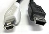
Mini-A plug (left), Mini-B plug (right)
Mini-USB connector pinout
| Pin | Function |
|---|
| 1 | VBUS (4.4–5.25 V) |
| 2 | D− |
| 3 | D+ |
| 4 | ID |
| 5 | Ground |
Most of the pins of a Mini-USB connector are the same as those in a standard USB connector, except pin 4. Pin 4 is called "ID" and, in the Mini-A plug, is connected to ground, but in the Mini-B plug it is not connected. This causes a device supporting USB On-The-Go (with a Mini-AB socket) to initially act as host when connected to a USB Mini-A plug (the "A" end of a Mini-A– Mini-B cable). The Mini-A connector also has an additional piece of plastic inside to prevent insertion into a slave-only (B-only) device.
USB connectors
Connector types
There are several types of USB connectors, and some have been added as the specification has progressed. From the original USB specification:
- Standard-A plug
- Standard-A receptacle
- Standard-B plug
- Standard-B receptacle
Added in the first engineering change noticed to the USB 2.0 specification:
- Mini-B plug
- Mini-B receptacle
Added in the Universal Serial Bus Micro-USB Cables and Connectors Specification:
- Micro-A plug (white)
- Micro-AB receptacle (gray)
- Micro-B plug (black)
- Micro-B receptacle (black)
Adapters, also from the Universal Serial Bus Micro-USB Cables and Connectors Specification (Note that no other adapters are allowed.):
- Standard-A receptacle to Micro-A plug
- "Micro-series USB technology will replace Mini-series USB in OTG products" [1] "Beaverton, OR, 2007-01-04 -- The USB Implementers Forum, Inc. (USB-IF) today announced the completion of the Micro-USB specification, a new connector technology that will replace many of the Mini-series plugs and receptacles currently used in portable products." The Micro-USB plug is rated for 10,000 connect-disconnect cycles. It is about half the height of the mini-USB connector in widespread use today but features a similar width.
Cables and connectors
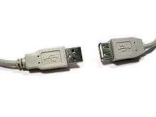
Series "A" plug and receptacle.
Cables have only plugs, and hosts and devices have only receptacles. Hosts have type-A receptacles; devices, if they have receptacles, have type-B. Type-A plugs only mate with type-A receptacles, and type-B with type-B.
The On-the-Go supplement allows a product to be either host or device, with a Micro-AB receptacle that accepts either a Micro-A plug or a Micro-B plug. Micro-A, Micro-B, and Micro-AB connectors are identified easily by color. The plastic inside Micro-A plugs and receptacles is always white, that in Micro-B connectors black, and that in Micro-AB receptacles grey.
There is a limited set of cables allowed by the USB specification. Cables fall into two categories — "detachable" and "captive". All allowed USB cables have one type-A plug, either Standard-A or Micro-A. The other end of a "captive" cable is either not removable or it has a custom connector on the device end. If the cable is "detachable", the other end of the cable must have a type-B plug. There also exists a special adapter cable that has micro-A plug and standard-A receptacle.
Captive USB cable types:
- Standard-A plug to device.
This cable may have a custom connector on the device end.
- Micro-A plug to device.
This cable is not intended to be removed by the end user of the device.
Detachable USB cable types:
- Standard-A plug to Standard-B plug.
This is the most popular cable for connecting USB devices to host.
- Standard-A plug to Mini-B plug.
Used to connect older mobile devices to host.
- Standard-A plug to Micro-B plug.
Used to connect newer mobile devices to host.
- Micro-A plug to Micro-B plug.
Used to connect mobile devices to each other.
- Micro-A plug to Standard-A receptacle.
This is a special adapter cable that is allowed to be at most 150 mm long. It is needed in order to allow mobile devices to act as USB hosts for devices which are not using Micro-USB connectors.
Any cable with a receptacle (except the special case above) or with two "A" or two "B" connectors is, by definition, not USB.
[6] However, many cable manufacturers make and sell USB-compatible (yet not strictly conforming) extension cables with a Standard-A plug on one end and Standard-A receptacle on the other end. Note that these non-conforming extension cables should not be mixed with conforming cables that contain a small bus-powered hub. Cables with two type A or even two type B plugs are available from more specialist suppliers.
Note that only "full-speed" and "hi-speed" devices use detachable cables. Compliant "Low-speed" devices only use captive cables, because the low-speed specification does not allow for the electrical characteristics of standard detachable USB cables.
The Mini-B, Micro-A, Micro-B, and Micro-AB connectors are used for smaller devices such as PDAs, mobile phones or digital cameras. The Standard-A plug is approximately 4 by 12 mm, the Standard-B approximately 7 by 8 mm, and the Micro-A and Micro-B plugs approximately 2 by 7 mm.
The connectors which the USB committee specified were designed to support a number of USB's underlying goals, and to reflect lessons learned from the varied menagerie of connectors then in service. In particular:
- The connectors are designed to be robust. Many previous connector designs were fragile, with pins or other delicate components prone to bending or breaking, even with the application of only very modest force. The electrical contacts in a USB connector are protected by an adjacent plastic tongue, and the entire connecting assembly is further protected by an enclosing metal sheath. As a result USB connectors can safely be handled, inserted, and removed, even by a small child. The encasing sheath and the tough moulded plug body mean that a connector can be dropped, stepped upon, even crushed or struck, all without damage; a considerable degree of force is needed to significantly damage a USB connector.
- It is difficult to incorrectly attach a USB connector. Connectors cannot be plugged-in upside down, and it is clear from the appearance and kinesthetic sensation of making a connection when the plug and socket are correctly mated. However, it is not obvious at a glance to the inexperienced user (or to a user without sight of the installation) which way round a connector goes, so it is often necessary to try both ways.
- The connectors are particularly cheap to manufacture.
- The connectors enforce the directed topology of a USB network. USB does not support cyclical networks, so the connectors from incompatible USB devices are themselves incompatible. Unlike other communications systems (e.g. RJ-45 cabling) gender-changers are almost never used, making it difficult to create a cyclic USB network.
- A moderate insertion/removal force is specified. USB cables and small USB devices are held in place by the gripping force from the receptacle (without the need for the screws, clips, or thumbturns other connectors require). The force needed to make or break a connection is modest, allowing connections to be made in awkward circumstances or by those with motor disabilities.
- The connector construction always ensures that the external sheath on the plug contacts with its counterpart in the receptacle before the four connectors within are connected. This sheath is typically connected to the system ground, allowing otherwise damaging static charges to be safely discharged by this route (rather than via delicate electronic components). This means of enclosure also means that there is a (moderate) degree of protection from electromagnetic interference afforded to the USB signal while it travels through the mated connector pair (this is the only location when the otherwise twisted data pair must travel a distance in parallel). In addition, the power and common connections are made after the system ground but before the data connections. This type of staged make-break timing allows for safe hot-swapping and has long been common practice in the design of connectors in the aerospace industry.
- The USB standard specifies relatively low tolerances for compliant USB connectors, intending to minimize incompatibilities in connectors produced by different vendors (a goal that has been very successfully achieved). Unlike most other connector standards, the USB spec also defines limits to the size of a connecting device in the area around its plug. This was done to avoid circumstances where a device complied with the connector specification but its large size blocked adjacent ports. Compliant devices must either fit within the size restrictions or support a compliant extension cable which does.
However, the physical layer is changed in some examples. For example, the IBM UltraPort is a proprietary USB connector located on the top of IBM's laptop LCDs. It uses a different mechanical connector while preserving the USB signaling and protocol. Other manufacturers of small items also developed their own small form factor connector, and a wide variety of these have appeared. For specification purposes, these devices were treated as having a captive cable.
An extension to USB called USB On-The-Go allows a single port to act as either a host or a device - chosen by which end of the cable plugs into the socket on the unit. Even after the cable is hooked up and the units are talking, the two units may "swap" ends under program control. This facility targets units such as PDAs where the USB link might connect to a PC's host port as a device in one instance, yet connect as a host itself to a keyboard and mouse device in another instance. USB On-The-Go has therefore defined two small form factor connectors, the Mini-A and Mini-B, and a universal socket (Mini-AB), which should stop the proliferation of proprietary designs.
Wireless USB is a standard being developed to extend the USB standard while maintaining backwards compatibility with USB 1.1 and USB 2.0 on the protocol level.
The maximum length of a USB cable is 5 meters; greater lengths require hubs
[2]. USB Connections can be extended to 50 m over CAT5 or up to 10 km over fiber by using special USB Extender products developed by various manufacturers.
Power supply
Standard
The USB specification provides a 5 V (volts) supply on a single wire from which connected USB devices may draw power. The specification provides for no more than 5.25 V and no less than 4.35 V between the +ve and -ve bus power lines.
Initially, a device is only allowed to draw 100 mA. It may request more current from the upstream device in units of 100 mA up to a maximum of 500 mA. In practice, most ports will deliver the full 500 mA or more before shutting down power, even if the device hasn't requested it or even identified itself. If a (compliant) device requires more power than is available, then it cannot operate until the user changes the network (either by rearranging USB connections or by adding external power) to supply the power required.
If a USB device sees that the data lines of the USB bus have been idle for 3 milliseconds, the device must go into suspend state. Suspended devices are allowed to draw 500 μA. If the device was configured to use more than 100 mA of current, before the device was suspended, and the device was configured as a remote wakeup source, the device is allowed to draw 2.5 mA while suspended. The current limits during suspend are one second averages.
Note that On-The-Go and Battery Charging Specification both add new powering modes to the USB specification.
If a bus-powered hub is used, the devices downstream may only use a total of four units — 400 mA — of current. This limits compliant bus-powered hubs to 4 ports, among other things. Equipment requiring more than 500 mA, hubs with more than 4 ports and hubs with downstream devices using more than four 100 mA units total must provide their own power. The host operating system typically keeps track of the power requirements of the USB network and may warn the computer's operator when a given segment requires more power than is available.


